Your antenna mount needs to be properly grounded for your antenna to function correctly. Without a solid ground, you're bound to get high SWR levels and extremely poor performance. Depending on where you have your mount installed and what your mount is made of, paint or a powder coating on the mount can prevent the mount from properly grounding to the vehicle.
To determine if a mount grounding problem is causing high SWR, you'll need to use a multimeter to check the resistance levels between the mount and the vehicle's frame. If you're not familiar with the concept of resistance or how to measure it, please refer to our guide on Understanding Electrical Resistance before reading further.
Step 1:
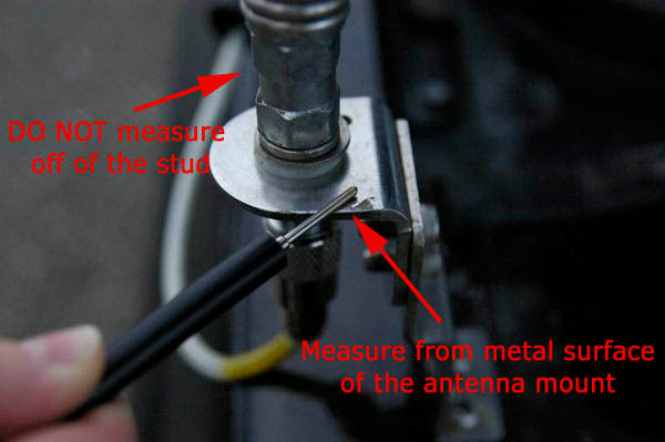
Touch one of your multimeter probes to a metallic portion of the mount as illustrated in Image 1. Make sure you DO NOT touch the stud portion of the mount, as it is SHOULD NOT be grounded -- it carries the current from the radio to the antenna.
Image 1: Measuring from the Mount (Top- and Center-Loaded Antennas)

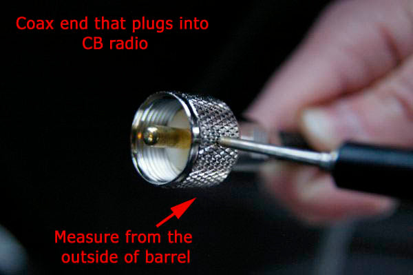
For Base-Loaded Antennas: If you're using a base-loaded magnet, trunk-lip or roof antenna, taking a measurement from the grounded mount will be more difficult, as it's usually on the bottom of the antenna and flush with the vehicle's surface. Instead of measuring from the mount as illustrated in Image 1, use the outside of the coax barrel which connects to the radio for your grounding measurement point as illustrated in Image 2. Make sure your antenna is installed to your roof or trunk when taking these measurements.
Image 2: Measuring from the Coax ( Base Loaded Antennas)

Step 2:
While keeping your probe on the mount (top- and center-loaded antennas) or coax barrel (base-loaded antennas), place your other probe on the black end of your battery as illustrated in Image 3. As all parts of a vehicle's chassis are grounded back to the battery, there will be continuity between the black terminal and anything connected to the frame of the vehicle.
Image 3: Measuring from the Grounded Battery Terminal


Step 3:
Keeping the probes pushed firmly against all surfaces, note the resistance reading on your multimeter.
Analyzing the Results and Identifying Problems
If there is little or no resistance, then you know the circuit is complete and you have a solid ground. If you're troubleshooting, you can continue with the knowledge that a grounding issue isn't your problem. If, however, the resistance reading doesn't change at all from the default open circuit setting, you don't have a solid ground, which is likely causing high SWR readings. You'll need to further isolate the problem in order to fix it.
For Antennas Using Individual Mounts: Chances are good that the problem is occurring at the mounting surface. Is there heavy paint that could be preventing a ground? Use your multimeter to measure any resistance between the mounting surface and the battery terminal. If you find resistance, you'll need to either scrape away the paint to create a metallic conductive surface or run a grounding wire from the mount to a grounded part of the vehicle. If you do run a grounding wire, keep it as short as possible.
If your mount is treated with a powder coating, there's a good chance the coating is preventing the mount to ground. You'll need to scrape away some of the coating in order to create a metal-to-metal connection or run a grounding strap to the body.
If you're still unable to find the problem, use your multimeter incrementally along every part of the connection (mount to mounting surface, mounting surface to grounded chassis surface, chassis surface to battery terminal) to determine what part of the circuit is open and thus preventing a ground.
For Base-Loaded Antennas: If you find that you have resistance, you'll need to determine where along the line the circuit is open. First off, test resistance between the metallic base of the antenna and the barrel of the coax. There should be no resistance, indicating continuity between the two. If there is resistance, you have a short in your cable and it needs to be replaced.
If the coax-to-antenna connection is fine, use your multimeter incrementally along every part of the connection (antenna base to mounting surface, mounting surface to grounded chassis surface, chassis surface to battery terminal) to determine what part of the circuit is open and thus preventing a proper ground.